
Finite-State Machines
An example of a shape-generic data structure

My involvement and interest with weave starts with finite-state machines. As a game developer, this is one of the most useful patterns out there. Most of what games are is overlapping and fine-tuned, synchronized finite-state machines. And yet, it’s quite hard to properly implement a FSM within a 13-week school course for some reason. The idea is just a bit too abstract, first in concept, and then in execution. Interestingly, any instance of a FSM is quite simple and can be hard-coded quickly. The proper abstraction, it seems, is playing hard to get.
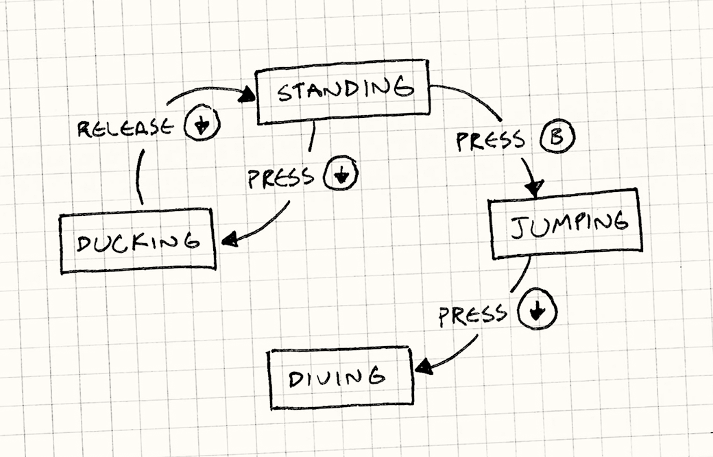
So, first, what’s an FSM, outside of our models? It’s a graph where every node is a state in which the “machine” can be in, and the directed edges are available transitions between those states. FSMs introduce some special terminology: we have a current state, which is where the machine is at the current moment, and a starting state which is the one that the current state will initialize to when the FSM is made. In a way, the whole operational semantics of a FSM consists of moving over several values in a constrained way: to implement this, you need an enum and several ifs. It’s easy to see why any specific version is simple.
The semantics of a FSM has its source in the starting state and, at any given point, leads to the current state, which is constrained to the set of states we begin with.
Here’s a weave-centric way to build a FSM. Let’s say I expect a standard graph from the user. This is usually passed through to the FSM as a hoisted graph: a single knot with hoisted arrows to all the states. This format is what we do for many of the other functions that require a custom graph, but in this case we can use the fact that the internals of a FSM have more strict expectations: we want our states to be a finite set, uniquely owned by the graph. We therefore can ask for a single knot with all the states represented via tethers to that knot.
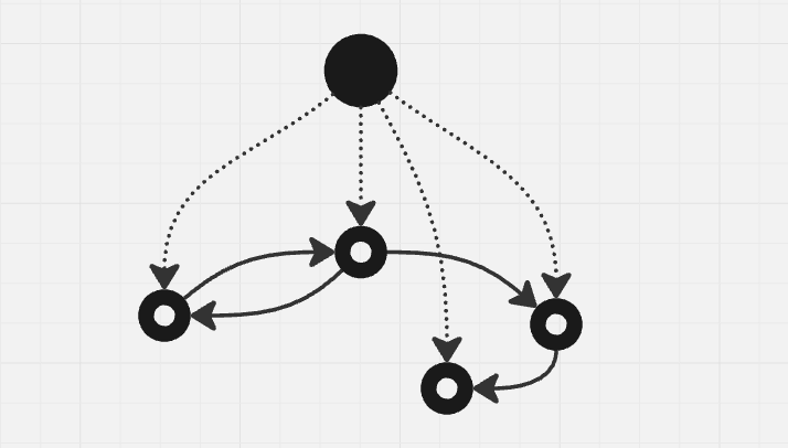
It’s worthwhile saying that the transformation of a standard hoisted graph G into a uniquely owned knot-tether graph is quite straight-forward and consists of taking the graph, going down the hoist to the member knots, making all of their sources be G, and then unhoisting them. All of these are standard weave functions, meaning that this operation is basically a one-liner. We can add checks to see whether any of the knots has multiple hoists leading to it, as we should quit early in these cases.
The Past and Present State
We’re currently taking care of the shape of the graph successfully, but we knew that we can draw a graph in weave. The question is what we can do with state and transitions. Initially, I found it very clear cut: we can just have a mark point to the current state, and one more to the starting state. The problem, however, isn’t in what we can do but rather how we can reach it at runtime. Starting with the top knot G, what do we have to do to get to the start state and the current state?
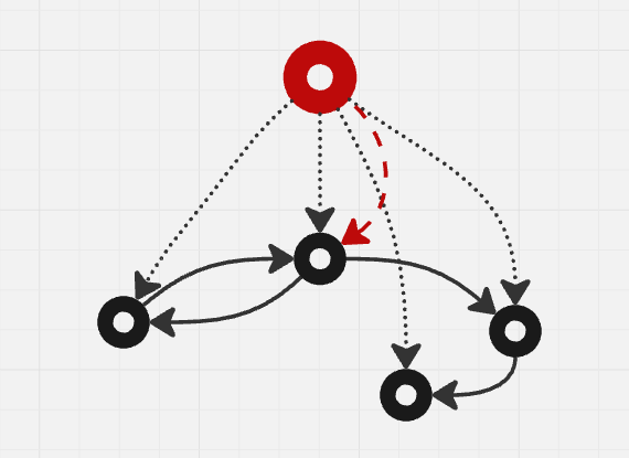
We could have these two be named arrows (arrows with some tag component) that lead to the states, for example. We could get to the current state by getting G and then asking for all arrows out, filtering out the one we want by component and getting the target of the arrow. In this regard, it seems start and current are isomorphic: the only difference in what data we set on them. Whenever I get to the point of things being equal up to data isomorphism, I know that we can weave further. For instance, let’s look at things functionally. The starting node should be the source of the state machine, we said previously, half in gross generalization and mid-hand-wave. But what if it was? What if instead of two arrows, we use the fact that the main knot G = G → G is… useless. What if we were to src(G) = start_node?
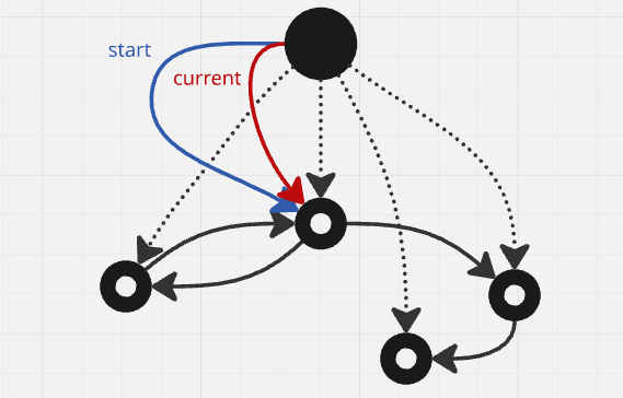
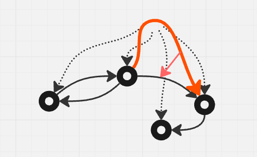
The main node G is now technically a tether of the starting state! Now, where does the FSM lead to? Well, our target always is to know in which state it currently is. So, what if we set tgt(G) = current_node? Let’s draw that first, without the image above, just to show off the idea:
Now, G is a mark of the current state. It is defined by its relation to this state in a way that allows us to always flow into it. Combining the two, we get a peculiar effect:
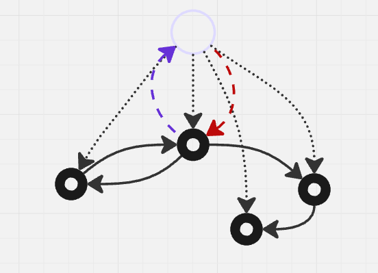
The source of G is the start state, the target of G is the current state. I’m doing you a courtesy by drawing the faint circle at the top but the truth is: the circle isn’t there. The entity G = start_node → current_node is no knot at all, nor mark, nor tether anymore. It’s an arrow!
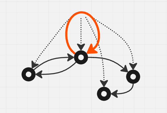
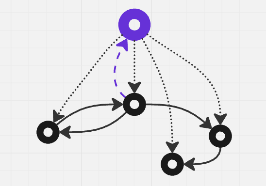
The pattern that emerges from a FSM seems to be an arrow that keeps its source in the starting node (which allows us to easily reset it too by saying tgt(G) = src(G)) and moving its target around only where the thing that it points to can move.
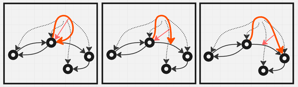
The actual moving around
The implementation of moving around the FSM requires components, albeit in a very simple way. When we want to move, we find the set of arrows_out of tgt(G). We filter that small set by the virtue of them having a certain component we’re looking for, finding the one arrow we need (and doing nothing if there’s none, or even if there’s more than one), and then searching for it’s target and setting tgt(G) = tgt(transition).
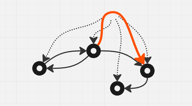
It’s important to remember that any entity is just a simple object that can be the source or target of any other entity. If we want, we can even trace in-between states by moving the FSM arrow to point towards the transition. If the previous state was a node, and the current is a transition, we’re transitioning-in, and if we’re on an arrow and moving onto a node, we’re transitioning-out. We can do this from code, but just for argument’s sake, if we really wanted to, we could even draw this into the graph as an arrow from our FSM arrow G to the last target it had…
Why is it important that we can do this? Well, I’ve asked myself that for a very long time. All of this seems very dumb when compared to the state of the art in bitflipping and bytecrunching. We need speed, and we need minimalist design, and we need it now. Yes. But until it’s good enough, we need to be able to debug. We need to be able to visualize, we need to be able to understand, and we’re overwhelmingly visual beings. Creating a weave allows us to save this complex state as neatly organized ECS storage, and present it visually, and have it be simple to manipulate. After it’s done, it can strip itself bare until the only thing left is minimalist code, and even then, annotating the code with comments that carry weave identifiers might be useful for later, for some very late reconstructions. If you really wanted to, you could make a chain of arrows pointing back through the history of changes, and it would cost exactly one entity per step. It could be a very fun ride!
Any program’s language’s semantics consists of going from one state to another following some allowed transition. All language semantics fit the bill for a FSM, no matter how large. Every language looks something like the image above. If you can trace this for your small game, you can trace it for any other program, including the compiler itself. That’s primarily why weave is there for structured debugging.
Shape-generics
Side-note about a distinction that’s very nitpicky. For a while now, I’ve been keenly aware that we can represent any data structure in weave. It’s not a surprise — we learn it in schools after all. We draw state after state until it clicks, and then we transcribe it into pointers and while loops. The thing that interested me was that, more and more, as I’ve gone further into weave, I’ve got the distinct feeling that FSMs are less of a design pattern, and more a data structure. Weird, huh? Here’s my reasoning. If I have an array, for example, which is undoubtably a data structure, and I index it at 0 and get the value back, then at 1, etc. If I introduce a test for when to increment (or decrement) the index, I’m technically doing the same thing we’re doing with the graph in FSM. The only big difference is that the shape within the array and the conditions within the tests make the transition function of their graph far less transparent. The design pattern within the array-and-conditions would at most be how we use them, and not the array itself. I think it’s then fair to say that the graph itself in the FSM has far less to do with the pattern. It’s much more obvious what’s happening in it, but that’s just because it’s a better carrier for the pattern.
Furthermore, I’d say that we can say FSMs are a structure that in its operations encodes the above-stated behavior. Just as lists can be expected to return a head and a tail, or an array can be indexed, or a lock-free structure can be compare-and-swapped, a FSM can take a value, compare it to a limited set of values at its current location and swap locations if the test succeeds. This is one of its only defining operations, most others being getters for the current or starting state. The closest thing the underlying structure needs to be is a set of states and “labelled” transitions, corresponding naturally to a graph, but almost any graph will do. This means that we can say the structure accepts a family of different shapes. In type lingo, we say that it would be generic in this parameter, the parameter being structure or even more precisely shape.
We can make very clear preconditions for what a correct generic structure would be. For example, we only want arrows between nodes, we want all the nodes to be tethers to the graph, all the arrows should be tagged with either some one data component, or different tags, and no two arrows going from a single node should be tagged the same. This is still an almost infinite number of graphs that fit the structure but have different shapes. Within all of them, once we feed the starting node and specific shape to the FSM data structure, we can call the trigger method on it as if we’d be calling a pop on a message stack. The pattern is now all about how we use this FSM data structure.